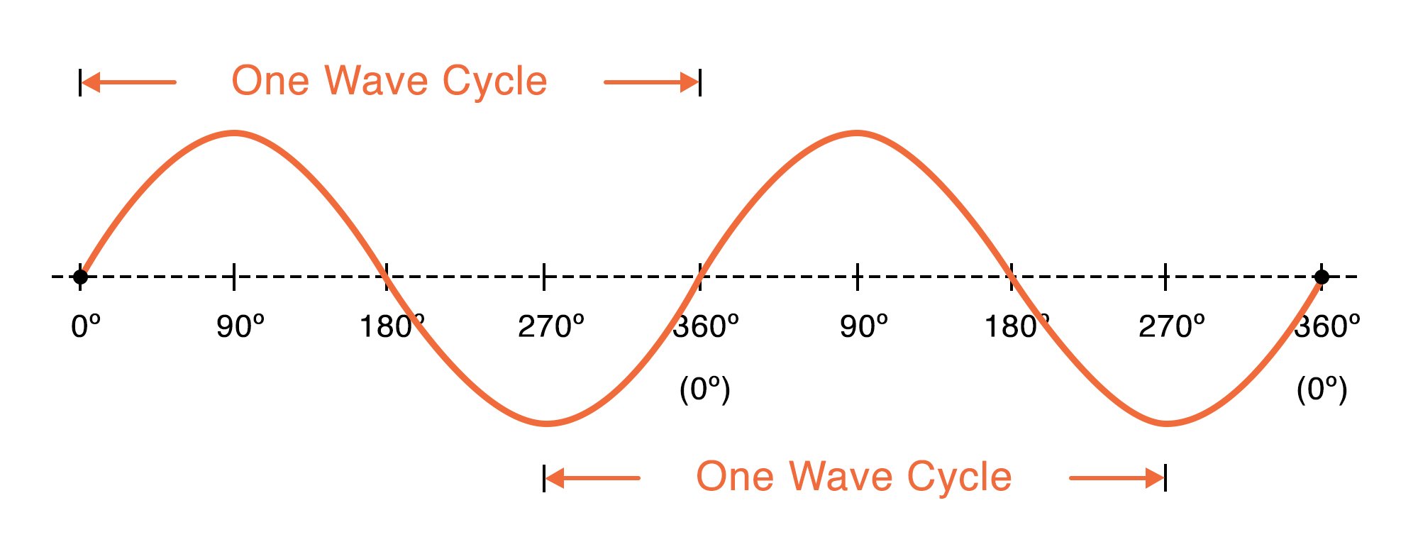
Characteristics of a Sinusoidal Ac Waveform
That is one cycle equals 360o. Lee A General Theory of Phase Noise in Electrical Oscillators IEEE JSSC Feb.
Characteristics Of Sinusoidal Signals Sine Waves Video Tutorial
But what would happen to the characteristics of the circuit if a supply voltage of fixed amplitude but of different frequencies was applied to the circuit.

. Delivers true rms or average rectified value of ac waveform Fast settling at all input levels Accuracy. The geometric properties of the rotor will determine the shape of the back-emf waveform. The back electromotive force is the voltage that occurs in electric motors when there is a relative motion between the stator windings and the rotors magnetic field.
Its steady-state is a time-varying waveform periodic Its response to external noises varies with time 1 20 1 2 14 A. Where necessary equipment manufacturers should specify the RCD Type required. The stray-loss factor for copper conductors varies as the square of the load current and the square of the frequency and will therefore vary with the harmonic mix in the power supply.
For our example we will put T 2π and fx I m Sinωt in the formula. Although the percentage contribution to distortion by higher harmonics decreases as the harmonic frequency rises its heating effect even if the harmonic. We have also seen in our tutorial about series RLC circuits that two or more sinusoidal signals can be combined using phasors providing that they have the same frequency supply.
The triangular waveform is the most commonly used carrier in the PWM technique for modulating AC voltage. Electrical Power in an AC Circuit. RMS Value of sinusoidal AC current is.
An AC-AC converter with approximately sinusoidal input currents and bidirectional power flow can be realized by coupling a pulse-width modulation PWM rectifier and a PWM inverter to the DC-link. In DC circuits the voltages and currents are constant and do not vary with time as there is no sinusoidal waveform function related to the supply. These waveforms can be sinusoidal trapezoidal triangular or something in between.
For example a waveform that begins at zero displacement and shows its initial movement upward has a phase of 0o a waveform that begins at maximum positive displacement and shows its initial movement downward has a phase of 90o and so on. Representing phase in degrees treats one cycle of the waveform as a circle. Typical SPWM technique uses the sinusoidal modulating waveform.
A sine wave sinusoidal wave or just sinusoid is a mathematical curve defined in terms of the sine trigonometric function of which it is the graphIt is a type of continuous wave and also a smooth periodic functionIt occurs often in mathematics as well as in physics engineering signal processing and many other fields. It is basically a voltage comparator whose output changes when the input signal crosses the. Cation of the AC line.
So long as it repeats itself regularly over time it is reducible to. 10 μV 025 of reading B grade Wide dynamic input range 100 μV rms to 3 V rms 85 V p-p full-scale input range Larger inputs with external scaling Wide bandwidth. Note that if the parallel circuits impedance is at its maximum at resonance then consequently the circuits admittance must be at its minimum and one of the characteristics of a parallel resonance circuit is that admittance is very low limiting the circuits current.
1 MHz for 3 dB 300 mV 65 kHz for additional 1 error. Unlike the series resonance circuit the resistor in a parallel resonance circuit has a damping effect on the circuits. These values are known as Instantaneous Values.
This is true no matter how strange or convoluted the waveform in question may be. PFC circuits which include active and passive PFCs shape and time-align the input current into a sinusoidal waveform that is in phase with the line voltage. For example the value at 1 millisecond will be different from the value at 12 milliseconds and so on.
This demonstrates how the shape of the waveform is affected on various types of circuits under load and fault conditions. The output waveform consists of a series of rectangular pulses with a fixed height and adjustable width. An op-amp detector that has the ability to detect the change from positive to negative or negative to a positive level of a sinusoidal waveform is known as a zero crossing detectorMore specifically we can say that it detects the zero crossing of the applied ac signal.
The inverter then changes the fixed voltage DC power to AC output power with adjustable voltage and frequency. The Type of RCD will depend on the characteristics of the equipment. Determine the time period T of waveform.
On the other hand different forms of modulating wave can be used according to the PWM technique. The output voltage waveforms of ideal inverters should be sinusoidal. Linear Time-Varying Oscillators are time-varying systems since.
The function of an inverter is to change a dc input voltage to a symmetric ac output voltage of desired magnitude and frequency. Type AC devices can detect and respond to AC sinusoidal wave current. It has been found that any repeating non-sinusoidal waveform can be equated to a combination of DC voltage sine waves andor cosine waves sine waves with a 90 degree phase shift at various amplitudes and frequencies.
The overall pattern of positive vs. The time period T of the waveform is 2π as evident from its waveform. Since an AC waveform is continuously changing its magnitude and direction the waveform at any instant will have a different value from its next instant.
The carrier wave usually has a much higher frequency than the modulating wave. Negative pulses is adjust-ed to control the output frequency. The DC-link quantity is then impressed by an energy storage element that is common to both stages which is a capacitor C for the voltage DC-link or.
A power factor correction PFC circuit is typically used to minimize the reactive power and maximize the available power from the source and distribution cabling. The DC output of the battery is bucked or boosted according to the requirement and then converted into AC using a DC-AC inverter. In contrast the instantaneous values of the current voltage and resulted power in an AC circuit are continually changing by the supply.

Sinusoidal Wave Signal Electrical4u
Measuring The Sine Wave
Ac Waveform And Ac Circuit Theory Of Sinusoids

Ac Waveform And Ac Circuit Theory Of Sinusoids
No comments for "Characteristics of a Sinusoidal Ac Waveform"
Post a Comment